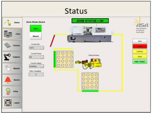
There is ever increasing value for Human Machine Interface tools that remove any perceived complexity for machine tool operators setting up and programming a robot cell for Machine Load and Unload tasks.
The human machine interface provides a graphic representation that allows the operator to monitor the machine with simplicity and ease and minimal training. ASA develops customised bespoke interfaces for its customer base, across various brands of machine tools. In this article, we will take a brief walk through one of these Human Machine Interface (HMI) tools, and highlight its benefits and ease of use.
A great user interface should be intuitive, easy to use and useful. The use of multiple screens with consistent and standardized layouts and displays with clear information and navigational links between screens helps to provide good visibility of the entire interface without being overwhelming to the user.
Zone Status Display (ZST)
The Zone STATUS Display, or ZST, is the main HOME screen for the cell, and provides the Alarm Status, as well as well as navigation to the associated sub menus. On the right-hand side of the ZST, there is functionality to allow for the cell to START, PAUSE, CONTINUE, ABORT, and FAULT RESET remotely without having to use the teach pendant. The screen can be configured as a touch screen, or on a PC using mouse, depending on the User’s preference.
When the robot isn’t being used, the CURRENT PART, CURRENT FIXTURE and CURRENT GRIPPER can be selected from the dropdown menus on the ZST, which are connected to Oracle XE Database. The information remains visible when running but can only be selected to edit when the cell is not being utilised. The same ZST screen also allows for an AUTO or MANUAL mode functionality, again without any requirement for accessing the robot teach pendant.
Parts Tab
Moving down the Sub-Menus on the left-hand side of the screen, the second menu is PARTS. This screen is the home for configuration of all parts, including the PART ID, PART TYPE, DESCRIPTION, PICK UP HEIGHT, PUT DOWN HEIGHT, UNLOAD CHUCK, CHUNK UNLOAD OFFSET, CHUCK LOAD OFFSET. Normally these items would have to be programmed with the robot, but the GUI creates a much smoother transition of human to machine interfacing, even for those with little to no robot expertise.
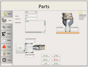
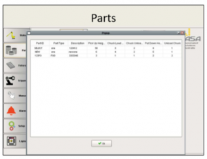
The User has an option of entering, editing and deleting any data, as well as setting CHUCK LOAD data where the machine is a twin spindle unit. On the SETUP Tab, the number of chucks that appear on the screen is configurable as 1 or 2, and the parts entered can be viewed from the TABLE button, which will provide sub-screen detail.
Fixtures Tab
The FIXTURES TAB allows the user to configure the fixture templates that align the parts on the pallets. The User enters the Fixture ID, number of units in X and Y Position, the relative X and Y offsets, and the X and Y spacing from the edge of the fixture. All of this data is then summarised in the TABLE. Pallet length, which is entered in PALLET SETTINGS under SETUP TAB, can also be viewed by accessing TABLE.
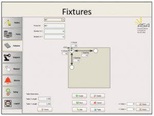
When the fixture is saved, the form automatically background checks that the full array of parts can fit on the pallet. The User can also request a manual check using the CHECK button. If the system determines that the parts won’t all fit, the User will be notified and the fixture configuration will not be recorded.
Grippers Tab
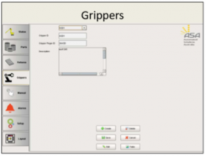
The GRIPPERS TAB allows the user to enter the GRIPPER ID, GRIPPER FINGER ID and DESCRIPTION into a table connected to database similar to PARTS and FIXTURES tables. The GRIPPERS ADDED to the system at any one point in time can be viewed from the Table button.
Manual Tab
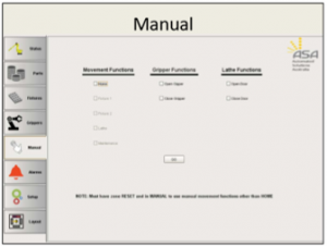
The MANUAL TAB gives the User access to Manual vs Automatic Control of the cell, primarily for robot movement and gripper functionality. Depending on the nature of the application, this screen can be customised to allow manual operation of the lathe functions to check the robot operation and feedback from the machine tool to the robot.
Setup Tab
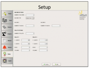
The SETUP TAB allows system settings and configurations to be altered. The NUMBER OF MACHINES can be selected, as well as the MACHINE TYPE (Brand), and then based on the number of machines, the number of associated CHUCKS can be entered for each unit. The MACHINE TYPE will alter the graphic on the main ZST screen, configuring it from a know array of loaded machine tools.
Layout Tab
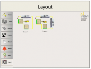
The LAYOUT TAB provides scope for the cell to be extended to include alternate layouts for future cell upgrades, and things of the like. These changes are accommodated at the initial setup, to minimise add on costs in the future when changes are likely.
As you can see from the walk-through of this typical HMI, minimal direct robot programming is required, and through the use of a smart human-machine interface, the cell is configured and setup with relative ease.
Human Machine Interfaces such as this example can be configured as part of a new system or can be completed as a retrofit to an existing system.
Please contact ASA on 1800 ROBOTS if you think this kind of software might benefit your organisation.
Send an enquiry:
Click an Application to Explore Further:
FANUC Robots Australia | Paint Robots for Surface Finishing | Welding Robots by FANUC | Machine Tool Tending Robots | Fibreglass and Gelcoat Robots | Palletising Robots | Robotic Vision Inspection Systems | Plastics Painting | Deburring and Polishing | Sealing and Dispensing | Picking and Packaging | Material Removal Robots | Shot Blasting and Peening |
More (Recent) News Stories from Automation Solutions Australia:
Deburring Machines | Robots a Historical Overview | Robotics Engineering | Automatic Paint | Robotic Loading Systems for CNC | Unlocking Your Manufacturing Potential | Spray Painting Robots | Automatic Sandblasting | CNC Mills | Automated Welding | Unlock the Future with Automation Systems | Robot Company, The Automation Era | Choosing an Automation Company | Harness the Power of Robotics with ASA | Robotic Painting | Automotive Welding | The Path to Machine Tool Automation | System Integrator Australia | Robotic Welders | Automate your CNC | Automation Company | Electrical Design | Human Machine Interface | Plastic Paint Robots | PLC Programming | Robotics Australia | Solutions | Industrial/Manufacturing Robots | Industrial Engineering | FANUC Robot | Shot Blasting | Robotic Automation Solutions | Industrial Automation | FANUC Industrial Robots | FANUC Collaborative Robots | FANUC Palletising Robots | Robotic Palletisers | Robotic Fibreglass Spray Machines | CNC Machine Automation | Robotic Arm – An Industry Guide | The Cobot | Automation Robotics | Custom Automation Solutions | Assembly Robots | Automate your Paint Booth | Ceramic Coating – Cerakote | Automotive Automation | Pick and Place Robots | Understanding Industrial Automation | PLC Automation | Arc V Spot Welding | What is Cerakote? | CNC Machines Australia | What is a Robotic Cell | Robotics Systems with ASA | What is ARC Welding? |PLC Controls | Collaborative Robots – What are they? | Welding Automation |


